Energy from the Sun drives many physical and biological processes and is increasingly important as a power source for human activities. The amount of solar energy reaching the top of the Earth’s atmosphere and its distribution across the electromagnetic spectrum is reasonably well known. It varies slightly over time, for some reasons that are predictable (e.g. distance of the Earth from the Sun), and for others that are not (e.g. solar flares & sunspots). The amount and spectral distribution of solar irradiance reaching the ground, on the other hand, is affected by atmospheric properties across a range of scales (aerosols to clouds), as well as the latitude of the site and the time of day.
Solar irradiance is measured with a device known as a pyranometer. The best pyranometers are uniformly sensitive to all wavelengths throughout the electromagnetic spectrum and are unaffected by the angle at which the Sun’s rays strike them. This is commonly achieved using a thermopile sensor designed to obey Lambert’s cosine law. Research-grade pyranometers based on thermopiles are very expensive. Fortunately, for many purposes a much cheaper solar sensor based on a photodiode can suffice, provided its limitations are understood. The lower cost of a photodiode-based instrument means that more can be deployed in the field, which means finer spatial detail and better replication. Also, for some purposes, notably solar energy potential, a photodiode instrument is preferable to a thermopile as its spectral response is very similar to that of a solar PV panel.
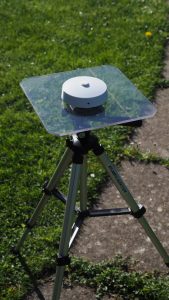
This page describes the design, construction and calibration of a low-cost solar sensor with a linear output over the range of solar irradiance encountered in nature.
The solar sensor was designed to fit in a plastic ceiling rose of the sort used in domestic lighting. This provides a neat, unobtrusive housing that is robust and can be made weatherproof if necessary. The picture shows the sensor mounted on a perspex sheet fixed to a photographic tripod. Two small spirit levels are used to ensure the sensor is horizontal.
Circuit design
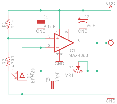
The photodiode is used in short-circuit mode to generate a small photocurrent which is fed to an operational amplifier (op amp). The op amp is configured as a transimpedance amplifier (aka current-to-voltage converter), with gain determined by VR1. Resistors R1 and R2 form a potential divider which introduces a small bias voltage (approx 25mV) into the op amp non-inverting input. Without this, the output of the op amp would approach the negative rail when there is no light falling on the photodiode. Some op amps become unstable or slow to respond under these conditions, so it is worth sacrificing a small amount of dynamic range to ensure stability.
The Maxim MAX406B op amp can operate on a single-ended supply as low as 2.5 volts, so no changes are needed to operate the solar sensor on a 3.3 volt supply. In this case, the bias voltage is approximately 15mV.
List of parts
D1: Vishay BPW20RF photodiode
IC1: Maxim MAX406B integrated circuit (DIL package)
VR1: 5kΩ 25 turn potentiometer
R1: 91kΩ
R2: 470Ω
C1: 0.1µF ceramic capacitor
C2: 10µF 16V tantalum capacitor
C3: 33pF ceramic capacitor
Small piece of stripboard
Ceiling rose
12mm diameter Teflon disc, 2mm thick (eBay)
Sugru mouldable glue
Construction
1. Disassemble the ceiling rose and reduce the height of the central collar to around 2mm. I did this using a Dremel cutting disc in a pillar drill to ensure that the cut surface was parallel with the base of the rose. [Please use eye protection if you use this method]
2. Use a round file to carefully increase the diameter of the hole in the rose until the BPW20 photodiode is a snug fit.
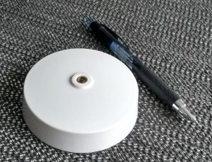
3. Remove the plastic sections covering the central area of the base of the ceiling rose.
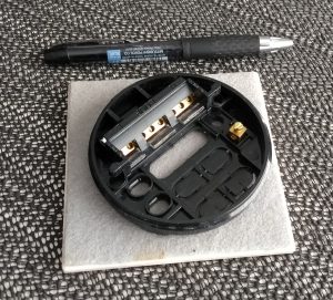
4. With the base inverted so that the connector block is exposed (see photo), screw it tightly into the cover. Draw a line across the hole to mark the required orientation of the leads from the photodiode, ensuring that the cathode (k) is on the right (see photo). The cathode of the photodiode is the large square plate.
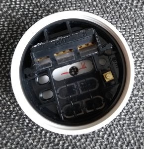
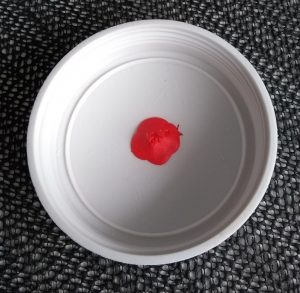
5. Next, unscrew the base. Take the cover and push the photodiode into the hole, with its leads aligned to the line you drew in (4). Secure the photodiode on the inside of the cover using a small amount of Sugru or similar. Set the cover to one side for the Sugru to cure.
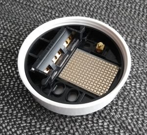
6. Cut a small piece of stripboard to fit in the well of the base, oriented and aligned so that the leads from the photodiode will pass through lines of copper (see photo). For the ceiling roses I use, a piece of 0.1″ stripboard 12 holes x 13 holes is needed.
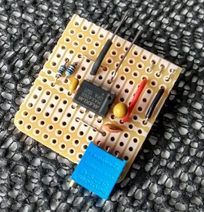
7. Assemble the circuit on the stripboard (without the photodiode). Note that the TMP36 temperature sensor and the photodiode go on the copper side. It’s a good idea to test the circuit with a spare photodiode before continuing with the next step.
8. Screw the inverted base into the cover and check that the photodiode leads are suitably positioned.
9. Locate the stripboard, making sure that the leads from the photodiode pass through the correct holes and that the TMP36 temperature sensor is suitably located. Mark the position of the multiturn potentiometer and drill a small hole through the ceiling rose so that the gain can be adjusted in use.
10. Solder the photodiode leads and add the wire connections between the stripboard and the connecting block (Vcc, GND and VOUT). Check that the gain potentiometer is accurately lined up before securing the stripboard with a dab of hot glue.
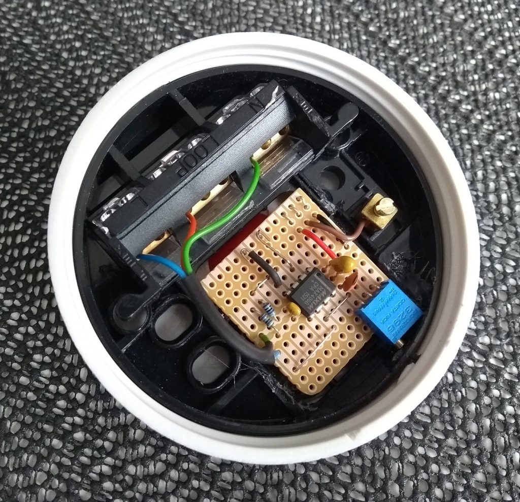
11. The final part of the assembly is the most difficult as it involves glueing a 12mm diameter Teflon disc over the photodiode to act as a diffuser. Teflon has very good diffusing properties and repels dirt and water, but it also repels most glues. However, it is possible to hold the disc in place with good quality contact adhesive or superglue. Take care not to contaminate the disc or the photodiode. An extra thin ring of Sugru can be added to provide weatherproofing if required.
12. That completes the construction of the solar sensor. All that remains is to add a four core connecting cable, three cores go to the connector block and the fourth to the output from the TMP36 temperature sensor.
Calibration
It is not easy to accurately calibrate a solar sensor without specialised equipment. However, with care and patience it is possible to achieve an approximate calibration, certainly good enough for amateur meteorological purposes. This is possible because photodiodes operated in short-circuit mode are highly linear over a wide range of illumination levels, so two calibration points are sufficient to define the relationship between solar irradiance and voltage.
The voltage output corresponding to zero irradiance can be used as the first calibration point. Note that this will not be exactly zero volts because of the small bias voltage deliberately introduced, amongst other things. Defining the upper point on the irradiance/voltage relationship is much more difficult but can be done in at least two ways. First, by comparison with a pyranometer which is known to be accurate. Second, by comparison with data from a model of solar irradiance at the ground, for example that available on the Apogee Instruments website. In both cases, a clear, cloudless day is required and the calibration is best done around noon when the solar zenith angle is changing slowly and in summer when the thickness of atmosphere between the Sun and the sensor is least.
Using the solar sensor with WeatherDuino
The standard solar sensor used in the WeatherDuino system is based on a design described by Charles Wright which uses a small silicon photovoltaic cell. There is some discussion in the WeatherDuino forum about alternative sensors, and in particular whether a photodiode could be used instead. There are pros and cons for each type of sensor in this application, and it is not the aim of this website to promote either, especially as both fall short of the standards required by a proper pyranometer. However, it may be of interest to WeatherDuino users to see a comparison between the WeatherDuino design and that described above. Example data obtained in the UK during the exceptional summer of 2018 are shown below:
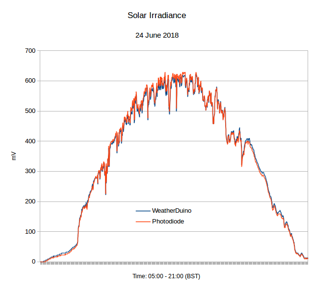
The sharp increase in irradiance early in the day is because the sensor was shaded by a building until around 7am. The time scale runs from 5am to 9pm (British Summer Time).
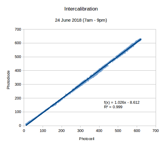
Sky conditions on the 24th June 2018 were exceptional for the UK, and these results show that the correlation between the photodiode instrument and the WeatherDuino solar sensor was almost perfect.